New Alco-Sensor III Calibration Procedure
Prior to calibrating an Intoximeters breath alcohol testing instrument, you should be trained to perform the calibration functions as allowed under your specific testing program. The calibration procedures below are designed to help you ensure precise and accurate test results. If, according to your program, you are not authorized to perform calibrations, please see your program administrator to determine the proper course of action.
DO NOT perform this procedure unless you are authorized to do so.
Below are basic calibration instructions for the Intoximeters Alco-Sensor III breath testing instrument.
Tools Required: Before beginning have these items available: instrument, calibration standard, new mouthpiece, non-metallic screwdriver.
New Alco-Sensor III Calibration Procedure Part 1
|
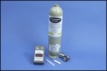 |
Note: A calibration standard can be a:
For this demonstration, a dry gas cylinder is used as the standard –value (at sea level) of .082%. a True-Cal Device was used to give the true value of the standard at the time of our demonstration – the True-Cal will adjust the expected gas value for the current atmospheric pressure. Therefore, the target value for this demonstration is .080. When to Perform a Calibration A calibration procedure should be performed when the result of an accuracy check indicates the unit does not read a standard within your testing program`s specified acceptable tolerance. |
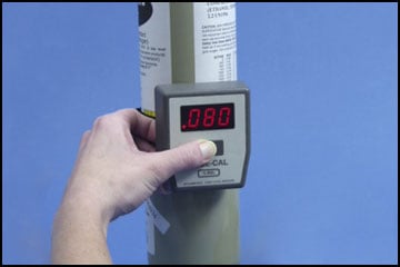 True-Cal displays .080 True-Cal displays .080 |
New Alco-Sensor III Calibration Procedure Part 2
| Prior to calibrating it is critical that you know and record the expected value of the calibration standard you are using. (The value of the standard will be found on the label on the Mini-Alco Can, Dry Gas Cylinder, True-Cal device (see previous picture) or Bottle of Wet Bath Simulator Solution). | |
| 1) Attach a clean dry mouthpiece. Check temperature of the Alco-Sensor III by depressing the READ and SET buttons at the same time. Be certain that the instrument temperature is between 15°C and 36°C. RELEASE READ button, SET button should remain depressed. (Note: The firmware version and revision designation will be displayed following the instrument temperature). | 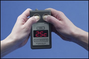 Temperature window |
2) Place the unit in CAL mode
|
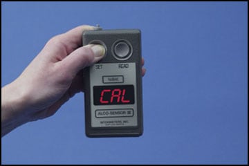 CAL is displayed |
| 3) CAL will be displayed momentarily before bLn appears on the display. (Note: Stop holding SET button down).
4) Depress READ button to take a blank test.
|
 bLn is displayed 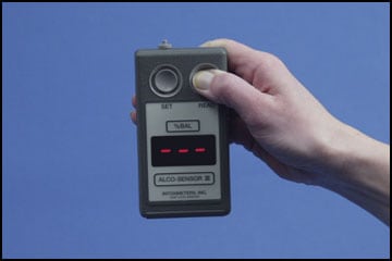 |
| 5) Depress SET button. CAL will be displayed in the dim mode. | |
New Alco-Sensor III Calibration Procedure Part 3
| 6) Attach your instruments mouthpiece to the end of the regulator line – small plastic tubing (this is referred to as the calibration assembly). Make certain there is a good seal between the connector and the mouthpiece. | 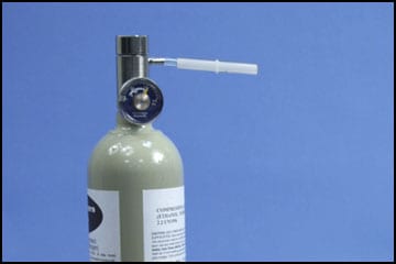 |
| 7) If you are using a dry gas standard,depress the button on the regulator for 6 seconds. (If you are using a Wet Bath Simulator & Solution for a standard, you should blow into the inlet port of the simulator for at least six seconds).Using either type of standard, on the 4th or 5th second of the 6 second count, press and release the READ button. | 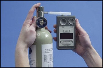 Regulator button depressed |
| (NOTE: The gas/vapor must be flowing through the mouthpiece when the READbutton is depressed and it is suggested that it flow for at least one second after the READ button has been depressed). | 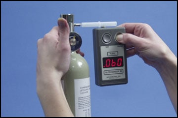
|
| 8) Carefully detach the Alco-Sensor III from the calibration assembly. Observe the display on the Alco-Sensor III. A moving dash — will appear on the display before the display shows the value used in the previous calibration (as long as the calibration screw has not been adjusted). If the displayed value is the same as the calibration standard you are currently using, proceed to step 10. If the displayed value is different than your current calibration standard, follow the procedure detailed in step 9.9) Place the screwdriver (must be non-metallic) in the calibration screw hole on the side of the instrument and turn the calibration screw until the reading on the instrument’s display is equal to the current target value of your standard. (Turn clockwise to increase the value; turn counterclockwise to decrease the value). Once this is accomplished remove the calibration screwdriver without further changing the displayed value on the instrument. | 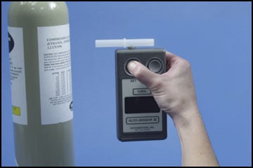 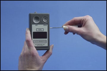 Screwdriver in screw hole |
New Alco-Sensor III Calibration Procedure Part 4
10) Depress the SET button. Your calibration is complete.
|

|
| 11) It is essential to verify the calibration. Wait 3 minutes then run an Accuracy check using a new mouthpiece. (Follow the step by step procedures described in the Post Calibration Accuracy Check).
The Accuracy Check reading following a Calibration should be within +.003 of the target value of the Calibration Standard. If it is not, wait another three minutes and then repeat the Calibration Procedure followed by an Accuracy Check. 12) Record the result.
|
- Date
- Time
- Procedure performed (Accuracy Check or Calibration)
- Name of Technician performing procedure
- Location
- Identification of the Standard including Lot Number of the Standard
- Expected Value of the Standard
- Result of the Accuracy Check or Calibration
For more information about procedures for your Intoximeters instrument, please refer to your
- Operator’s Manual
- or email Intoximeters Tech Support
- or phone the Technical Support Department at (314) 429-4000